I R Temperature Readings on Sailboat Engines
Engine Temp Monitoring And Overheating Assessment
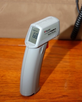
An Infrared Thermometer
This is an infrared thermometer and it is what I consider to exist an important tool for any boat owner. As I always say "tools are free". What I hateful past this is the expense of the tool, and doing the job yourself, is near always paid for by the labor savings. In 35 years of tool buying I accept nevertheless to notice i that was non paid off in one or 2 projects or uses. Lucky for the average gunkhole owner infrared thermometers, as well called pyrometers, have come up way down in price over the concluding 4-5 years.
In that location are lots of things an infrared thermometer can exist used for on a boat such equally refrigeration trouble shooting, stuffing box trouble shooting, electrical trouble shooting and information technology has plenty of uses for engine problem shooting. You can too aim it at the bounding main, earlier jumping in, to avoid the "I was in the pool." / shrinkage argument.
What is engine temp monitoring and why am I reading this?
I wanted to pass forth my process and pre-planning assessment for potential future overheating events. By following these procedures you will be able to problem shoot over heating in your ain engine based on the baselines you create before a trouble arises.
This measurement process should accept place well before you've had an overheating state of affairs and is the whole premise of this commodity. It'south to get a baseline when your engine is running well.
You'll employ the infrared thermometer to measure various marked locations on the engine prior to an overheat so that when yous take one you tin can pull out your notebook, tablet or computer, compare measurements, and more quickly isolate and locate the problem.
We'll call this our engine temp baseline;
Your engine temp baseline should always be derived from a properly running engine with a clean sea-strainer, clean estrus exchanger (HX), make clean unclogged frazzle elbow and a new or relatively new impeller. Measurements should only be taken after the engine is 100% warmed up from having been run under load long enough to bring the h2o heater temp as high as the engine normally gets under cruising load.
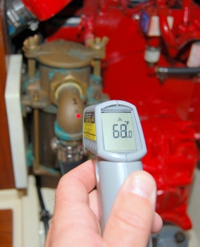
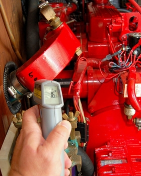
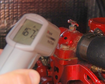
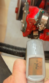
Measuring the Raw H2o Intake Temp
Here I'm measuring the temperature of the elbow leading to the sea strainer. It tells me the Atlantic Bounding main under the boat is 68 degrees and that means the temp my raw water pump sees is also 68 degrees.
Take this reading and salvage information technology to a Give-and-take doc. or only write information technology in a notebook. This is not a critical reading just nice to know each fourth dimension you check. If the h2o temp was 32f then I would non expect the same temps elsewhere on the engine simply if it's within 5-eight degrees all your other readings should autumn in line.
Every spot I mensurate on an engine gets a corresponding number and a dot made with a Sharpie marker. I use the dot and then I tin get repeatability whenever I aim the thermometer.
Please try to use roughly the aforementioned aiming distance when taking measurements. Consistency with an infrared thermometer will atomic number 82 to more accurate readings. If you used a 6″ distance when creating the baseline stick with a 6″ distance in the future.
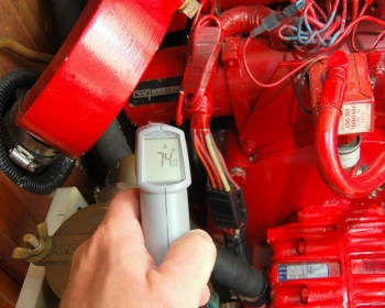
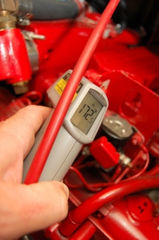
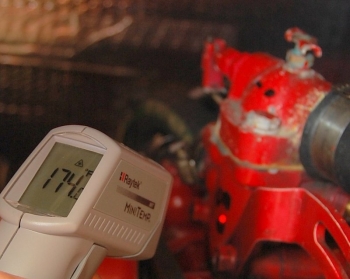
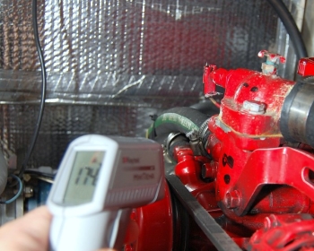
Heat Exchanger Raw Water Outlet to Manual Cooler
Here I'thou reading the temp of the raw water circuit on it's way out of the HX.
The raw water path on this Westerbeke engine is equally follows;
- Raw Water Seacock To Bounding main Strainer
- Sea Strainer to Raw Water Pump
- Raw H2o Pump to Heat Exchanger Intake,
- Heat Exchanger Outlet to Transmission Cooler Inlet
- Manual Cooler Outlet to Siphon Break,
- Siphon Intermission to Exhaust Elbow.
Please IGNORE the temp readings on my Raytek Infrared as I did not have the fourth dimension to properly warm up my engine. They are illustrative but! I already had these numbers recorded and but wanted to photograph how to get your engine temp baseline.
Measuring the raw water temp at the cease of the HX
In this photo I'm measuring the temp in the cavity at the opposite end of the HX where the zinc goes. This is a raw water temp measurement.
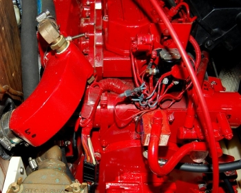
Measuring The Wet Side of the Frazzle Elbow
This is the exhaust elbow. The frazzle elbow serves the purpose of injecting cooling water into the hot exhaust gasses then they can be expelled through the rubber hoses, inside your boat, without melting them.
In this photo you tin easily come across my numbering system and the dot for repeatability.
The brass elbow coming into the summit side of the exhaust elbow is the injection point for the raw water (ocean or lake h2o) circuit. This is where the water that gets spit out your transom gets injected into the exhaust system to go on information technology cool.
This temp, and the side by side one, are very critical measurements. Exhaust elbows, on curt run time sailboat installed diesels, tend to load upwards with rust scale and carbon until they become blocked or clogged. A blockage of the exhaust elbow tin can definitely cause an over heating event.
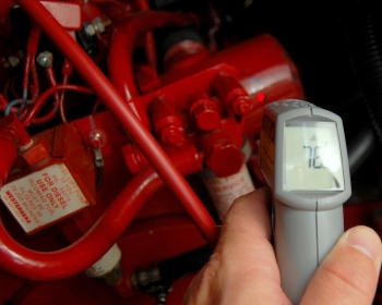
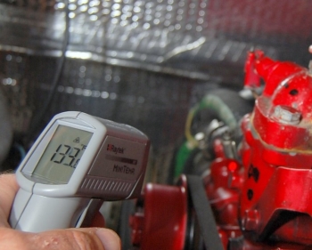
Measuring the Dry Side of the Frazzle Manifold
On this Westerbeke, and most other diesel fuel engines, the frazzle injection elbow is bolted or welded directly to the exhaust manifold. This measurement is to measure out how hot the actual dry frazzle gasses are before they are mixed with raw cooling water..
As you lot can see in that location is nigh a 100 degree drop in exhaust gas temp after the water injection indicate. This reading is a little depression for this engine but again this was for illustrative purposes merely. The temps on this engine would really be of fiddling use for your engine anyway.
If this measurement, and the differential temperature between the wet and dry side of the exhaust elbow begins to get progressively wider, and hotter and hotter, information technology' a good indication you take an injection elbow offset to clog up.
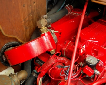
Injection Signal and Measurement Dot
This is just a wider angle photo of the injection to the exhaust elbow and the dot I aim the infrared at to get good repeatability.
Exhaust Manifold and Injection Elbow
Simply some other angle of the manifold feeding into the injection elbow and the raw water hose injection point.
Measuring the Thermostat Housing
In this photo I'm measuring the temperature of the upper thermostat housing.
I know the cherry laser dot is off slightly from my dot simply holding the DSLR photographic camera, with a hot shoe flash, and the infrared while upside down and contorted leaves it upwardly to; close enough is good enough, for this illustration.
NOTE: The petcock mounted to the top of the thermostat housing is where you would bleed any trapped air off the sealed or anti-freeze side of the system to prevent an air lock. Some engines take this feature & some don't. On some engines this petcock is just in a different location.
WARNING: Before attempting a bleed a petcock moisten a rag with COLD water then y'all don't burn your fingers and wear insulated fishing gloves made of safe. The antifreeze can burn you if you are not careful. I recommend a cold rag over the petcock, rather than pliers considering it tin spray out at a high strength. Trust me, you don't want to use just pliers with no rag to forestall spray while upside down and contorted. Ouch!
Measuring the Depression Side of the Thermostat Housing
This should be self explanatory as I'thousand measuring both sides of the thermostat. Comparing these two numbers volition requite y'all an idea of how the t-stat is operating and at what temps it's opening and closing.
With all these measurements it'southward a good idea to measure out them over about a 3-five minute menses and then record a low and loftier reading for each location then you take a baseline range.
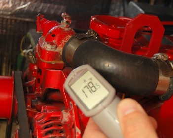
Measuring the Temp of the Sending Unit
In this photo I am measuring the actual temperature of the sending unit where it threads into the engine block. The t-stat on this Westerbeke is rated at 180 and the Raytek reads 178.5. Keep in mind t-stats are non all that accurate and tin can have every bit much as a 5+ degree variance.
Over again, monitor this reading for a while to get a low normal range and a high normal range for your baseline.
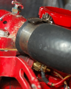
Close Up of Temperature Sending Unit
This contumely sensor with the wire attached is what I was aiming at in the last photo. This is the unit of measurement that sends the temperature to the temperature gauge on your engine panel.
Measuring The Raw Water Pump
The impeller is lubricated & cooled by the sea or lake water that it'south pumping. It'due south a good thought to get a baseline reading on this equally well. If you develop and blockage of your intake or sea strainer the temp of the raw water pump tin can climb due to decreased water flow and thus less cooling.
It volition unremarkably read a little hotter than the ocean temp as measured on the outlet side and this is normal. This temp differential, fifty-fifty with a brand new impeller, should still be under a ten degree spread.
Measuring the Hot Water heater Supply Line
In this photo I am measuring the temp of the supply to the hot water heater.
Measuring the Return Line From the Water Heater
As y'all can encounter in this photo, based on the differential, the hot water heater is not withal up to temperature. I have about a forty degree differential temperature across the supply and return lines for my water heater.
The water heater acts like another rut exchanger and can really throw off your readings and overheat findings. Your supply and returns from the water heater should exist within near 5 degrees of each other before creating your baseline cess.
I often hear "My engine runs fine for nigh 30-40 minutes then begins to overheat?". This could simply exist a state of affairs of a clogged HX, sea strainer or other raw water excursion problem getting masked past the cool water in the water heater. This cool water acts like, and can mimic, a rut exchanger. Every bit the temp in the heater rises the engine can no longer dissipate heat into that water and the engine begins to over heat.
Don't forget to write all these numbers downwardly with both your high normal and low normal range readings. When or if you have an over heating state of affairs yous can now easily trace it by comparison these numbers to the measurements / readings taken during an over estrus.
Proficient luck & happy boating!
Source: https://marinehowto.com/engine-temp-monitoring-and-overheating-assessment/
0 Response to "I R Temperature Readings on Sailboat Engines"
Post a Comment